A inverted pendulum using arduino and Grove-sensor
DESCRIPTION
Inverted pendulum is a device to show the beauty of balance. Showing what control algorithm can do? It‘s a very popular device in the robot-control academic field. You can find the complete definition here https://en.wikipedia.org/wiki/Inverted_pendulum I built this open-source inverted pendulum in order to help the peopel who is fascinated with robot control building their own inverted pendulum easily. All the source code including the inverted pendulum library are accessible on my GitHub repositories.
DETAILS
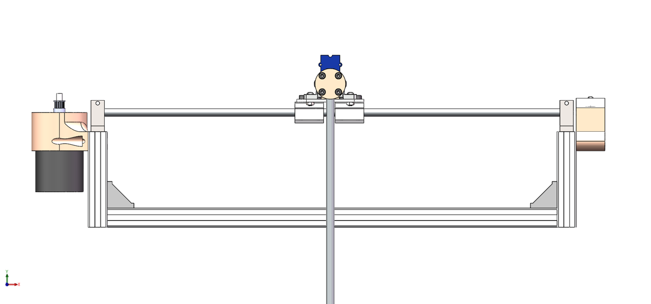
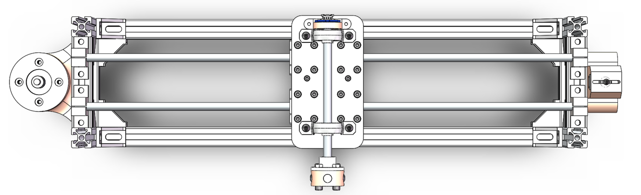
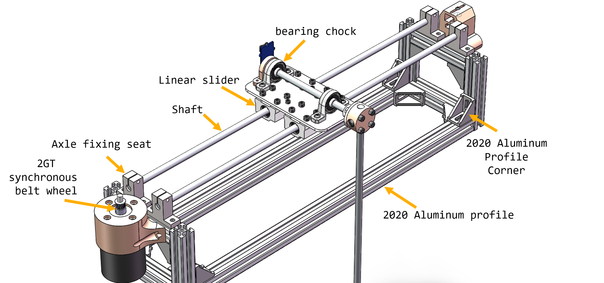
About the mechanical structure
I built this inverted pendulum using some standard mechanical structure except the 3D printed parts.
You can find all the standard component in hardware store.
About the PID control algorithm
You may familiar with the following picture. Yeah, It's a sketch map about PID control algorithm.
The beginners always spent a lot of time to figure out how PID control algorithm work. To make things simpler. I write a inverted pendulum arduino library. You can get the library from my github repository. Using that library you can build your own inverted pendulum without struggling with the code.
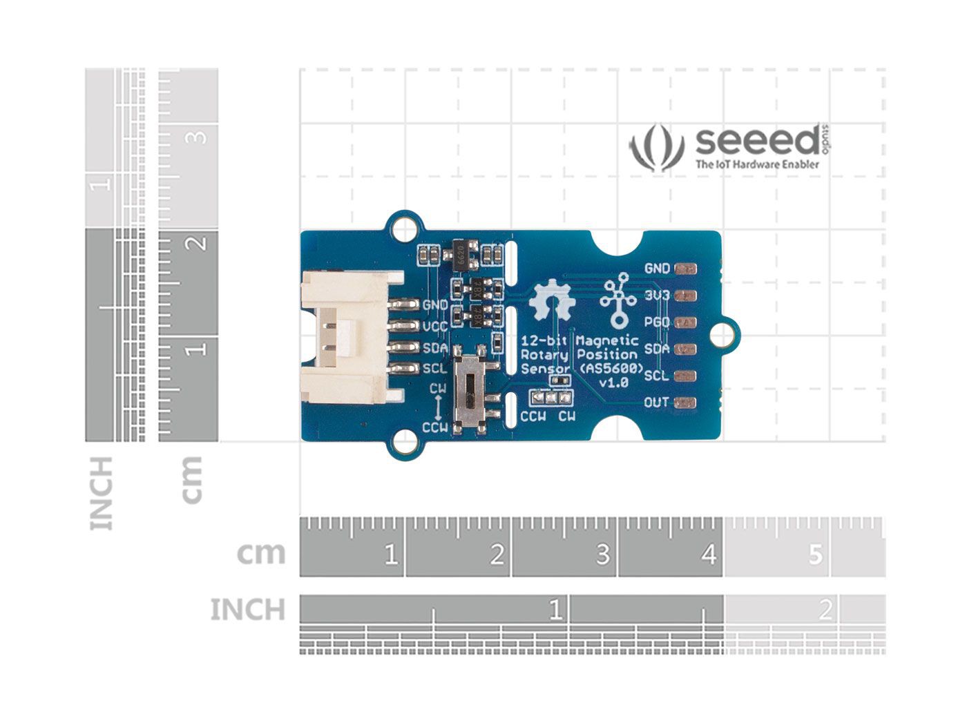
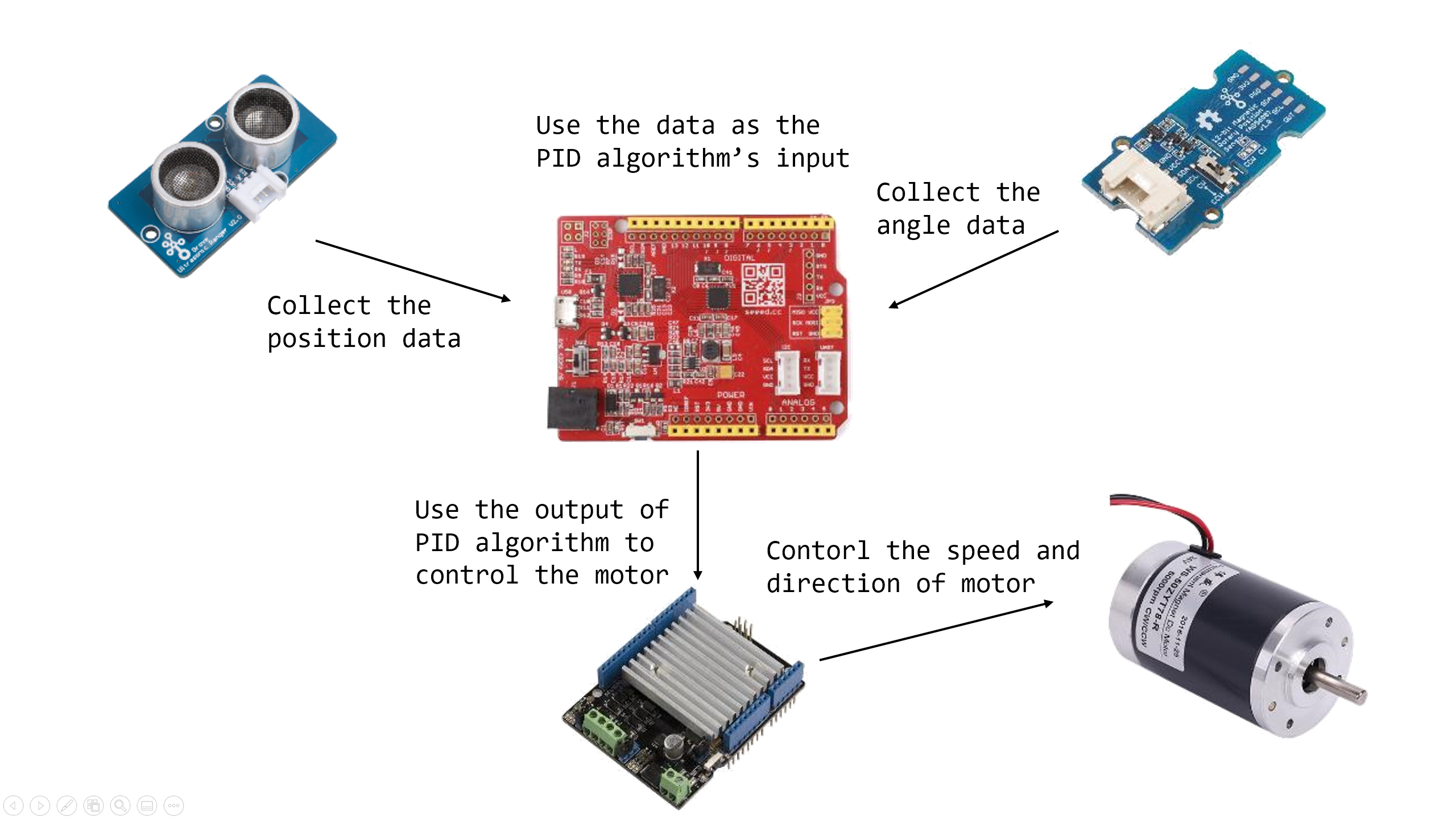
I use Grove - 12-bit Magnetic Rotary Position Sensor /Encoder (AS5600) andGrove - Ultrasonic Distance Sensorto collect the angle and position data as the feedback of contorl algorithm.
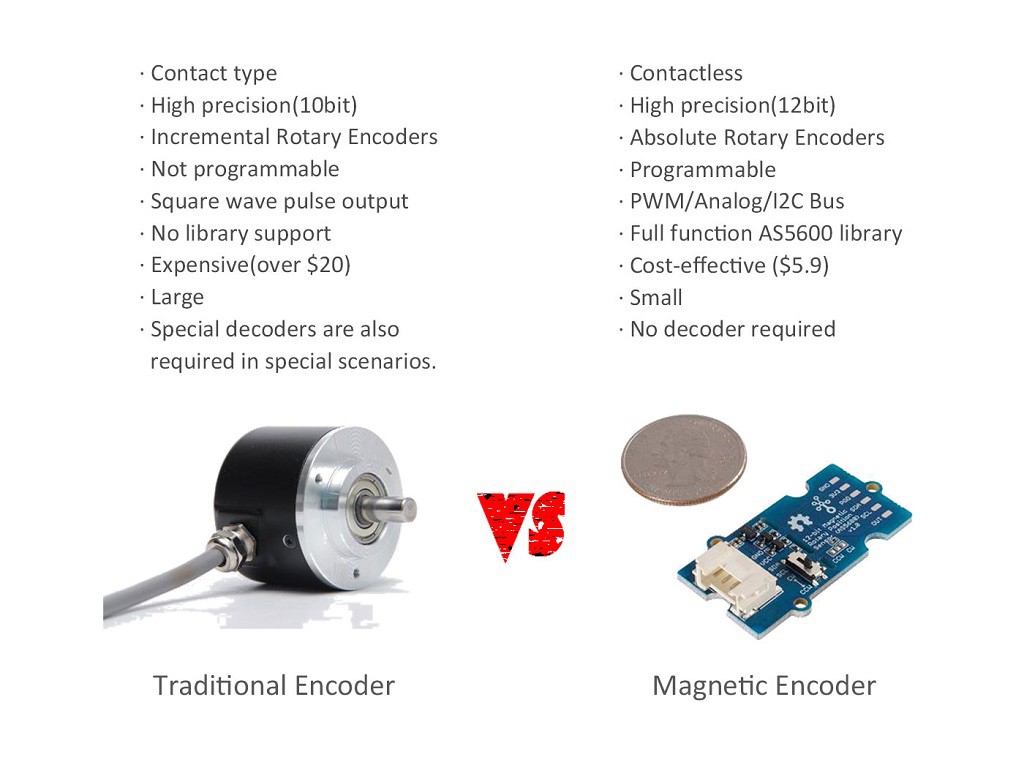
We all know about the potentiometer, quoted from Wikipedia "A potentiometer is a three-terminal resistor with a sliding or rotating contact that forms an adjustable voltage divider." Simply put, the potentiometer converts relative position information into electrical signals. But the traditional potentiometer needs to be in contact with the object being measured. What about scenes that need to be contactless, such as high-speed motor, or high-precision robot arm? Well, the answer to the contactless potentiometer solution is the Grove - 12-bit Magnetic Rotary Position Sensor (AS5600).
The Grove - AS5600 is a programmable 12-bit high-resolution contactless magnetic rotary position sensor. The Grove - AS5600 can work as magnetic potentiometer or magnetic encoder with excellent reliability and durability. Compared with the traditional potentiometer/encoder, the Grove - AS5600 has significant advantages: high precision, non-contact, no rotation angle limitation. All those advantages make it is perfectly suitable for non-contact angle measurement applications, such as the robot arm, tripod head, motor closed-loop control, machine tool axis positioning.
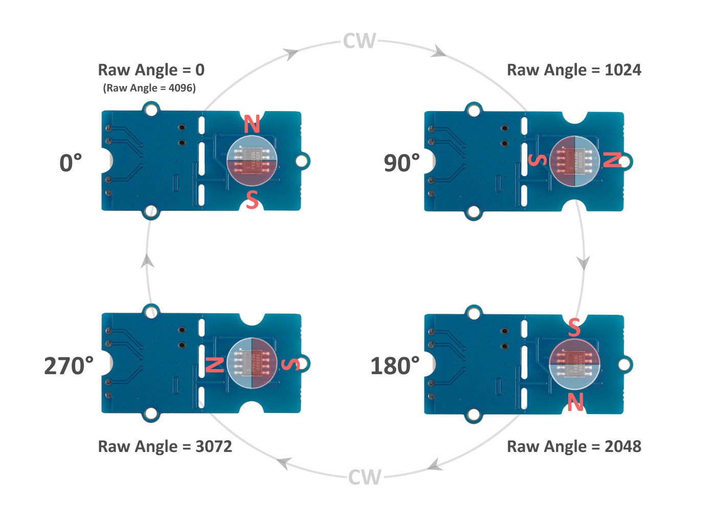
AS5600 is based on the Hall Effect, the build-in Hall sensor can detect changes in the direction of the magnetic field, thus, there is also no rotation angle limit. Then the magnetic field direction information is amplified by the amplifier, with the help of the build-in 12 bit A/D, the AS5600 module can output 4096 positions per round. The output is selectable, you can either use the I2C interface to output the RAW data or output the PWM wave/Analog wave via the OUT pin. Meanwhile, the maximum angle is also programmable, you can set the maximum angle from 18° to 360°, which means that the measured angular accuracy is up to 18/4096.
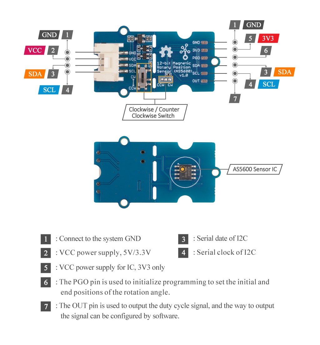
AS5600 is excellent for the non-contact rotary position sensor, so seeed made this AS5600 Breakout Board in the Grove form factor. With the Grove I2C connector, you can easily connect this AS5600 module to Arduino. Also, we provide the full function AS5600 Arduino library.
Attention
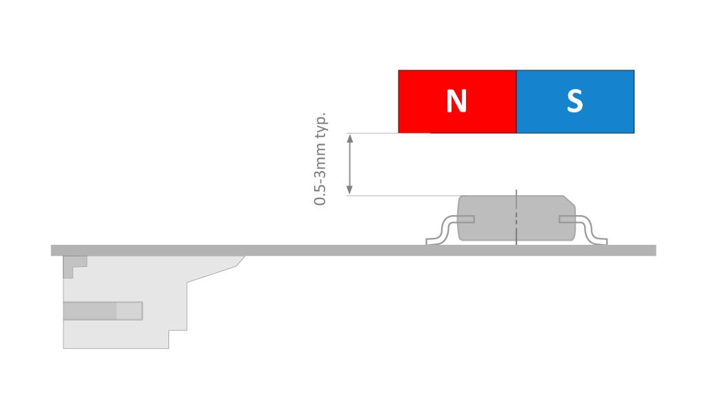
The AS5600 has certain requirements for the magnetic field to be measured. Please use a magnet similar in size to the chip. The module should be measured as close as possible to the magnetic field and the AS5600 sensor center should be aligned with the center of the magnetic field. The vertical distance is preferably from 0.5 mm to 3 mm.
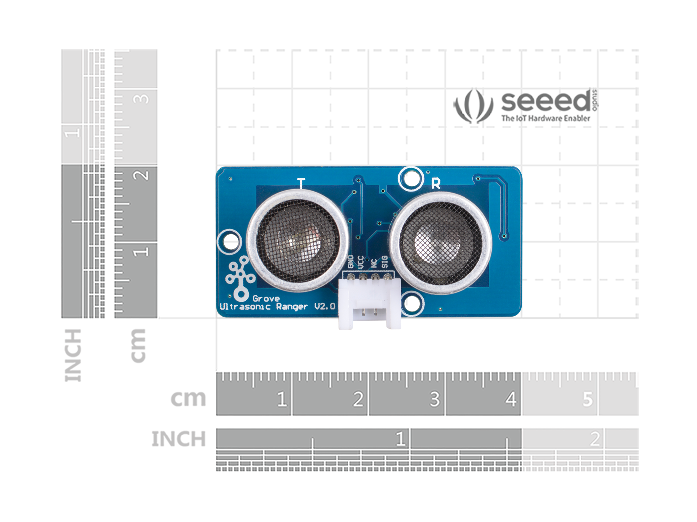
The Grove - Ultrasonic Distance Sensor is an ultrasonic transducer that utilizes ultrasonic waves to measures distance. It can measure from 3cm to 350cm with the accuracy up to 2mm. It is a perfect ultrasonic module for distance measurement, proximity sensors, and ultrasonic detector.
This module has an ultrasonic transmitter and an ultrasonic receiver so you can consider it as an ultrasonic transceiver. Familiar with sonar, when the 40KHz ultrasonic wave generated by the transmitter encounters the object, the sound wave will be emitted back, and the receiver can receive the reflected ultrasonic wave. It is only necessary to calculate the time from the transmission to the reception, and then multiply the speed of the sound in the air(340 m/s) to calculate the distance from the sensor to the object.
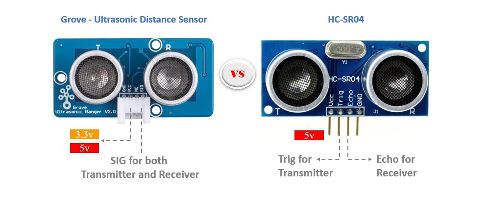
Compared with traditional ultrasonic modules HC-SR04, the Grove - Ultrasonic Distance Sensor integrates a single-chip microcomputer, and the transmitting signal and the receiving signal share one pin by time division multiplexing, so only one I/O pin is occupied. Another difference is that HC-SR04 only supports 5v voltage, while Grove - Ultrasonic Distance Sensor supports 5v and 3.3v. As we know, the Raspberry pi I/O only supports 3.3v. Therefore, Grove - Ultrasonic Distance Sensor can be directly connected to the I/O of the Raspberry Pi, but HC-SR04 needs to use a voltage conversion circuit.
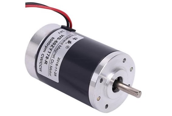
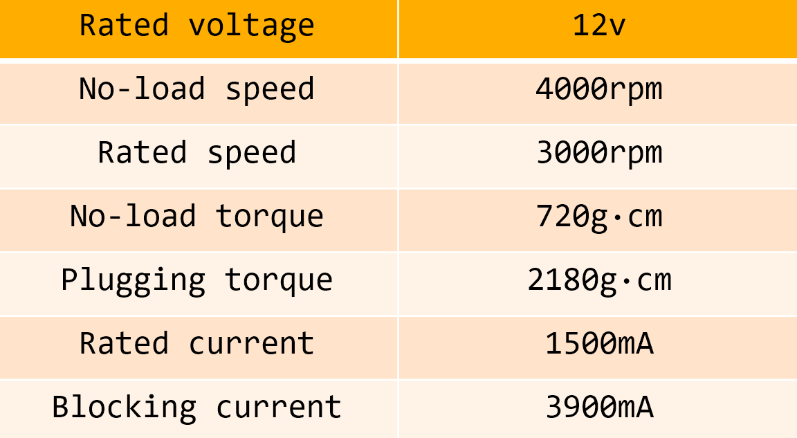
The motor I used is this guy. Its model is WS-50ZYT78-R


Comments
Post a Comment